Load Cell Adc Calculation

Loadcell Sensor 24 Bit Adc Hx711 Sensor Arduino Electronic Parts

A Reference Design For High Performance Low Cost Weigh Scales Analog Devices

Arduino Lm358 Pwm To Adc Functional Description Arduino Converter Electronic Kits

Which Adc Architecture Is Right For Your Application Analog Devices

Ac Current Measurement Using Arduino And Hall Effect Sensor Acs712 Arduino Hall Effect Sensor

10 Things You Can Do With Your Hx711 And Load Cell Latest Open Tech From Seeed Studio

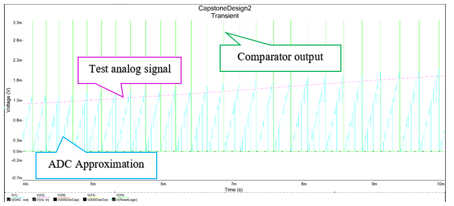
From equation 42 and supplying the values determined for a 2mv v sensitivity and 10kg load cell you should be able to achieve better than 1g resolution using the settings shown in this application.
Load cell adc calculation.
The Abcs Of Analog To Digital Converters How Adc Errors Aff

Amazon Com Knacro Hx711 Adc Converter Breakout Module Digital Load Cell Weight Sensor 20kg Portable Electronic Kitchen Scale Diymall For Load Cell Weight Weighing Home Audio Theater

Hx711 How To Measure In Correctly Blog Sketching With Hardware

Hx711 24 Bit Analog To Digital Converter Adc Pinout Datasheet Features

Types Of Adcs And Dacs Maxim Integrated

Resistive Bridge Basics Part One Maxim Integrated

Arduino And Visuino Measure Weight With Hx711 And Load Cell Hackster Io

Amazon Com Noyito 1kg 5kg 10kg 20kg Load Cell And Hx711 Combo Pack Kit Load Cell Amplifier Adc Weight Sensor 20kg Hx711 Electronics

Arduino Adc Aref Arduino Chapter Tutorial

Flow Chart Of C Code For Spirit Level Indicator Pic Microcontroller Levels Flow Chart
12 Bit Tracking Small Signal Adc Hackaday Io

Degraw 40 Kg Tension Load Cell And Hx711 Combo Pack Kit Load Cell Amplifier Adc Weight Sensor For Arduino Scale Everything Needed For Accurate Force Measurement Amazon Com Industrial Scientific
How To Use Load Cell With Hx711 And Arduino Microcontroller Tutorials

Tutorial To Interface Hx711 Balance Module With Load Cell 9 Steps With Pictures Instructables

Adc Input Noise The Good The Bad And The Ugly Is No Noise Good Noise Analog Devices
Https Www Mdpi Com 2079 9292 9 5 757 Pdf

Analog To Digital Converters Ee Times

Make Your Weighing Scale Hack Using Arduino And Hx711 Automacao

8 Channel 12 Bit Adc For Raspberry Pi Stm32f030 Seeed Wiki
How To Choose The Right Daq Hardware For Your Measurement System Ni
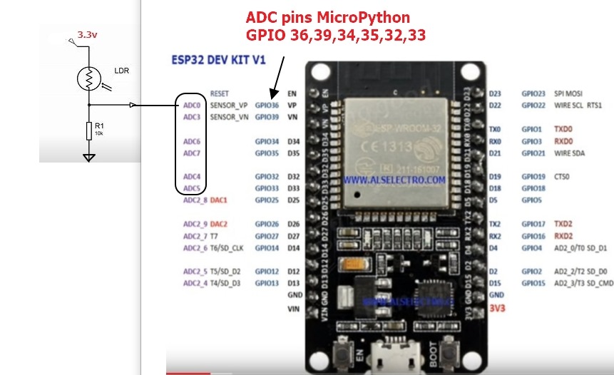
Esp32 Micropython Adc With Analog Sensors Alselectro

Load Cell With Adc Output At Rs 590 Piece Load Cells Id 12734051112
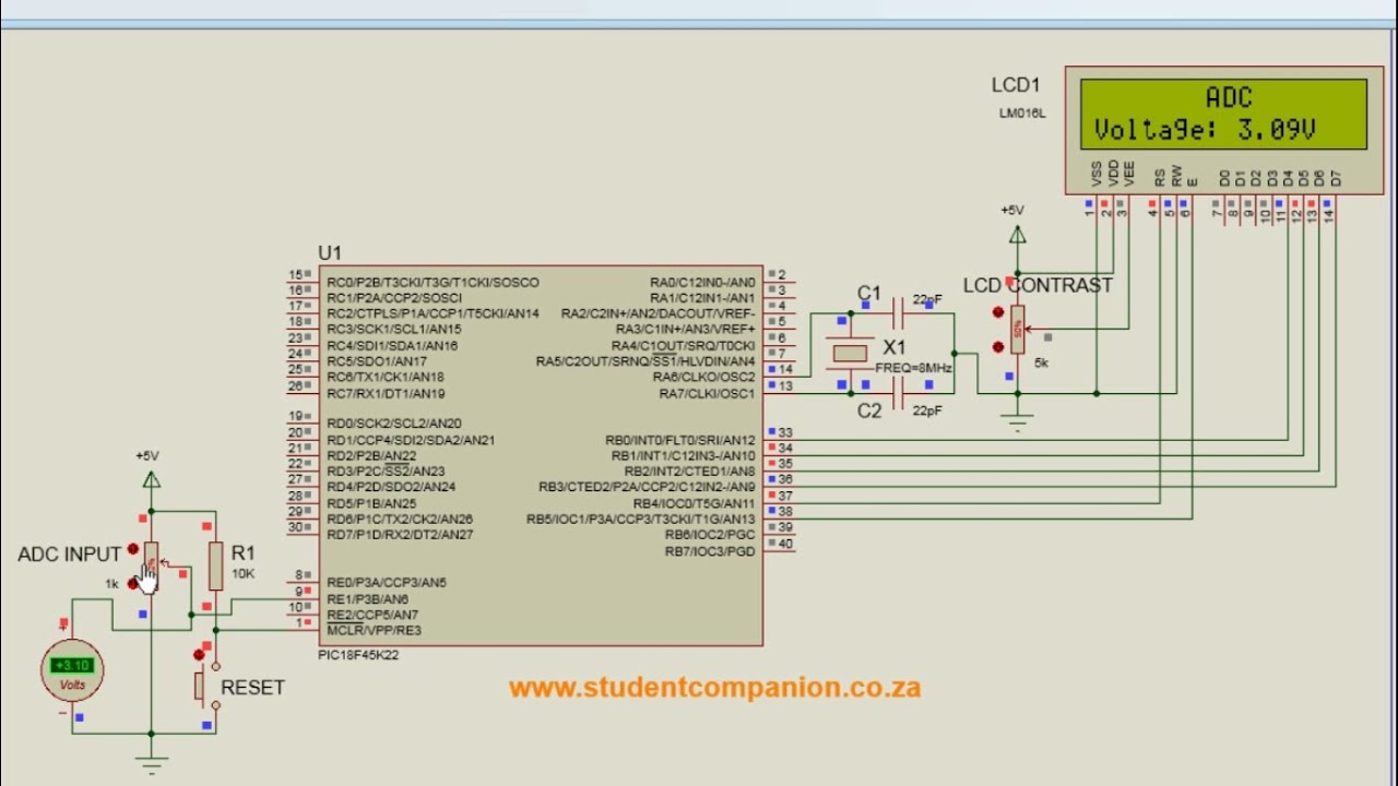
6 Analog To Digital Converter Mikroc Pro For Pic Tutorial Youtube

Build Your Own Digital Weighing Machine Full Electronics Project In 2020 Weighing Machine Electronics Projects Circuit Diagram
Source : pinterest.com
